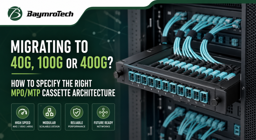
Introduction:
Why Does Cassette Architecture Matter During Network Migration?
Migrating a data center network to 40G, 100G or 400G Ethernet involves more than replacing switches and optical transceivers. The underlying fiber infrastructure must support the selected optical interfaces, fiber paths, connector arrangements and transmission requirements without introducing unnecessary complexity.
An MPO/MTP cassette can help organize high-density fiber connections by transitioning between a multi-fiber trunk and supported connector interfaces, such as duplex LC connections. However, the correct design depends on the actual optical application, not simply the network speed printed on the equipment specification.
An incorrectly specified cassette may result in mismatched connectors, unsuitable fiber mapping, excessive optical loss, unusable ports or costly cabling rework. These problems become particularly challenging when an existing data center must support multiple generations of Ethernet equipment while maintaining service continuity.
For procurement teams, the challenge is to balance immediate connectivity requirements with future migration plans. A solution that works for one duplex application may not be suitable for a parallel-optics application requiring multiple fiber lanes. Similarly, a cassette that fits the rack enclosure may still be incompatible with the installed trunk cable or transceiver interface.
The objective is to specify a complete, compatible optical path from transceiver to transceiver, with the cassette treated as one component of that path.
This guide explains how to evaluate MPO/MTP cassette architecture, fiber mapping, polarity, optical loss and procurement requirements for 40G, 100G and 400G data center deployments.
2. What Is an MPO/MTP Cassette?
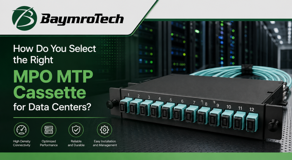
An MPO/MTP cassette is a fiber connectivity module designed to simplify connections between multi-fiber trunk cabling and one or more supported connector interfaces.
In a typical structured cabling arrangement, a multi-fiber trunk connects to the rear of the cassette. Internal fiber routing presents the individual fibers at the front through connectors selected for the intended application, commonly LC duplex interfaces in appropriate designs.
A cassette-based design can help organizations:
- Organize dense fiber connections within limited rack space.
- Simplify the management of trunk cables and front-panel patching.
- Establish a consistent, documented fiber mapping scheme.
- Support planned changes to connectivity when the selected cassette architecture is appropriate.
- Improve circuit identification and maintenance workflows.
However, not every cassette converts an MPO/MTP trunk into LC duplex ports. Other configurations may expose different interfaces or support specific parallel-optics arrangements. The intended transceiver application and the cassette’s documented design must determine the selection.
MPO versus MTP: What should buyers know?
MPO refers to a standardized family of multi-fiber push-on connector interfaces. MTP is a branded connector system designed to conform to applicable MPO interface requirements while incorporating its own design features.
Although MTP connectors are commonly used within MPO-based infrastructure, buyers should not assume that every connector combination will deliver the same mechanical fit, alignment, performance or compatibility. Connector gender, guide-pin arrangement, key orientation, fiber count and manufacturer specifications all matter.
When specifying a cassette, identify the required connector interface and mating conditions rather than relying on the terms MPO and MTP alone.
For product evaluation, start with the BaymroTech MPO/MTP solution range and confirm the exact configuration required for the deployment.
3. Understand the Network Application Before Choosing a Cassette
Network speed is an important starting point, but it does not uniquely determine the cassette design. Several technical factors must be considered together.
Target Ethernet application and transceiver
Determine the Ethernet standard or application and the exact transceiver interface at each end of the link. Different optical interfaces can use different numbers of transmit and receive lanes, fiber types and connector arrangements even when they operate at the same nominal network speed.
Parallel optics versus duplex transmission
Duplex optical connections generally use separate fibers for transmission and reception. Parallel optics uses multiple optical lanes across a group of fibers, with the required arrangement depending on the application.
A duplex LC cassette may be suitable for an application designed around duplex LC transceiver interfaces. A parallel-optics application may instead require a compatible multi-fiber interface or a specifically engineered breakout arrangement.
Required fiber count
Calculate the number of fibers needed for the selected application, including transmit and receive paths where applicable. Then verify that the cassette, trunk cable and patching arrangement support the required count and mapping.
Unused fibers do not automatically make a design future-ready. Their usefulness depends on connector configuration, routing, polarity, fiber type and the planned application.
Single-mode versus multimode fiber
Single-mode and multimode systems use different optical characteristics and application requirements. A cassette must match the fiber type and the intended transceiver application throughout the link.
Existing infrastructure and future topology
Document the installed trunk cable, connector interfaces, panel format and link topology. If the migration includes breakout connections, leaf-spine connectivity or a change from duplex to parallel optics, establish the complete end-to-end fiber plan before selecting hardware.
A cassette should therefore be selected against a documented application and topology, not a speed label in isolation.
4. Technical Factors to Specify Before Ordering
A technically complete specification reduces the risk of receiving a cassette that fits the panel but fails to meet the network’s optical or connectivity requirements.
1. Connector type and fiber count
Specify the required MPO/MTP connector interface, fiber count, connector gender where applicable, and whether the connector uses angled or flat physical contact. The trunk, cassette and mating component must be compatible. A 12-fiber connector and a 16-fiber connector are not interchangeable simply because both use a multi-fiber format.
2. Cassette input and output interfaces
Identify the trunk-side connector and the equipment-side interface. Specify whether the design requires LC duplex ports, a multi-fiber interface, or a supported breakout configuration. Confirm the internal fiber mapping and port arrangement in the product documentation.
3. Fiber type and optical application
State single-mode or multimode fiber and the relevant fiber category where applicable. Confirm that the cassette, trunk, patch cords and transceivers support the intended Ethernet application and reach. Cable jacket colour alone is not sufficient proof of fiber type.
4. Polarity and fiber mapping
Define the end-to-end transmit-to-receive mapping. Document the selected polarity method and verify every connection across trunks, cassettes, patch cords and transceivers. This is particularly important for parallel-optics links and breakout connections.
5. Insertion loss and connector inspection
Specify the allowable component loss and the complete channel loss budget based on the selected transceiver application. Request applicable test results and connector inspection procedures. Do not assume that a low-loss label alone guarantees compliance with the link budget.
Additional specification details
- Keying and mating compatibility: Confirm key orientation, pin configuration, connector polish and the required mating adapter. Do not force incompatible connectors together.
- Port density and enclosure: Check cassette dimensions, panel compatibility, access for patching and space for cable routing.
- Trunk compatibility: Match the cassette to the existing trunk’s connector count, fiber type, polarity and length requirements.
- Labeling and circuit identification: Define port labels, trunk identifiers and the naming convention used in the network documentation.
These details are important for commissioning, fault isolation and future changes. A clear specification also allows procurement teams to compare quotations on equivalent technical terms.
5. Planning for 40G, 100G and 400G
The following table compares representative Ethernet optical applications. These are examples of common architectures, not a universal mapping for every transceiver operating at the stated speed.
| Application | Representative optical architecture | Typical fiber/interface approach | Cassette planning implication |
| 40GBASE-SR4 | Four transmit and four receive optical lanes | Multimode fiber, 8 active fibers, MPO interface | Verify the multi-fiber path and mapping; a duplex LC cassette is not automatically suitable. |
| 100GBASE-SR4 | Four transmit and four receive optical lanes | Multimode fiber, 8 active fibers, MPO interface | Confirm fiber category, connector requirements and end-to-end polarity. |
| 100GBASE-LR4 | Four wavelengths multiplexed over a duplex link | Single-mode fiber, duplex LC interface on typical implementations | A compatible duplex connection may be appropriate; an MPO cassette is not inherently required. |
| 400GBASE-SR8 | Eight transmit and eight receive optical lanes | Multimode fiber, 16 active fibers, MPO-16 interface | Confirm 16-fiber connector compatibility and the exact cassette or trunk architecture. |
| 400GBASE-DR4 | Four transmit and four receive optical lanes | Single-mode parallel optics, commonly MPO-12 with eight active fibers | Verify connector polish, active fiber positions, mapping and transceiver requirements. |
| 400GBASE-FR4 | Four wavelengths multiplexed over a duplex link | Single-mode fiber, duplex LC interface on typical implementations | A compatible duplex path may avoid unnecessary multi-fiber conversion. |
Application examples are based on published Ethernet and transceiver documentation. Connector options, reach and breakout capabilities must be confirmed against the exact transceiver model and vendor specifications.
What do these differences mean for buyers?
40G deployments: A 40GBASE-SR4 connection is a parallel-optics example using eight active multimode fibers. Buyers should verify that the complete path supports the required transmit and receive mapping rather than treating the connection as a standard duplex link.
100G deployments: 100G can use different optical architectures. For example, 100GBASE-SR4 uses parallel multimode fibers, while 100GBASE-LR4 uses wavelength multiplexing over a duplex single-mode connection. The required cassette architecture therefore depends on the selected transceiver.
400G deployments: The variation becomes even more important. 400GBASE-SR8 uses an MPO-16 interface, while representative 400GBASE-DR4 and 400GBASE-FR4 implementations use MPO-12 and duplex LC interfaces, respectively. Other 400G optics may use different connectors or lane arrangements.
A planned breakout from one higher-speed port to multiple lower-speed ports introduces additional requirements. The transceiver must support the intended breakout mode, and the cable assembly, cassette and fiber mapping must match that arrangement.
For migration planning, document both the initial configuration and the intended future configuration. Then determine whether the existing passive infrastructure can support the future link without replacing incompatible components.
6. Polarity, Fiber Mapping and Compatibility
Polarity describes the relationship between transmit and receive paths across a fiber link. In a duplex connection, the transmitting side must connect to the receiving side at the far end. Parallel-optics systems require the correct mapping of multiple transmit and receive fibers.
Suggested visual: illustrate the selected polarity method and fiber mapping for a specific documented link. Do not use a generic diagram as a universal wiring instruction.
How to avoid common polarity mistakes
- Document the complete channel. Record the source transceiver, trunk, cassette, patch cords, destination cassette and receiving transceiver.
- Confirm the mapping at each transition. Connector labels alone may not reveal the internal cassette wiring or trunk polarity.
- Check connector gender and key orientation. Physical mating compatibility does not, by itself, prove correct optical mapping.
- Verify breakout configurations separately. Each destination port must map to the intended optical lane and transceiver.
- Test before production use. Validate continuity, polarity and optical performance using methods appropriate to the installed link and application.
There is no single polarity method that should be prescribed for every MPO/MTP architecture. The correct method depends on the connector interfaces, component wiring, optical application and end-to-end topology.
7. Optical Loss and Quality Verification
Optical loss is a critical factor when specifying high-density fiber connections. Every connector, adapter, splice and fiber segment can contribute to the total loss of the channel.
Buyers should evaluate two related but different requirements:
- Cassette insertion loss: The loss attributable to the cassette under the specified test conditions.
- End-to-end channel loss: The combined loss of the complete optical path, including all applicable components and fiber segments.
The transceiver’s supported channel budget determines whether the assembled link can operate within its specified limits. A cassette that meets its own component specification may still form part of a channel that exceeds the overall loss budget.
Before approving a quotation, request the applicable insertion-loss specification, testing conditions, connector inspection requirements and available test documentation. Where required by the project, define end-to-end insertion-loss testing and polarity verification as acceptance criteria.
Connector end faces should be inspected and cleaned using appropriate procedures before mating. Contamination can increase loss and cause performance issues even when the components are otherwise compatible.
Avoid specifying an arbitrary insertion-loss figure without first checking the application, connector configuration and test method. Acceptance criteria should be tied to the intended optical link rather than a generic product description.
8. What Should Buyers Include in an MPO/MTP Cassette RFQ?
An effective request for quotation should define the required configuration clearly enough for a supplier to evaluate compatibility, identify missing technical information and prepare a comparable offer.
Rather than requesting a generic 40G, 100G or 400G cassette, include the following project details.
| RFQ requirement | Information to provide |
| Network application | Ethernet standard, intended use and target speed |
| Transceiver | Exact model or complete optical interface specification |
| Fiber type | Single-mode or multimode, including category where applicable |
| Connector interfaces | Trunk-side and equipment-side connectors, fiber count, gender and polish |
| Cassette configuration | Port count, interface arrangement and required mapping |
| Polarity | Required method and documented end-to-end mapping |
| Optical performance | Applicable insertion-loss limits and channel loss budget |
| Mechanical requirements | Panel or enclosure format, dimensions and port density |
| Quantity | Initial order quantity and anticipated project requirements |
| Quality documentation | Applicable test reports, inspection records and acceptance criteria |
| Identification | Port labels, circuit references and packaging requirements |
| Commercial details | Samples if needed, delivery location, requested lead time and quotation validity |
Questions to resolve before approving the order
Ask the supplier to confirm the proposed cassette’s compatibility with the specified transceiver interface, trunk assembly and patching arrangement. Request a configuration drawing or fiber mapping schedule where the design requires it.
For a migration project, also clarify whether the quotation covers only the cassette or the associated trunk cables, adapters, patch cords and other connectivity components.
Sample approval may be useful for projects with specific mechanical or mapping requirements. However, a sample should be evaluated against the documented specification, not accepted solely because it physically fits the panel.
9. How BaymroTech Fits into Your MPO/MTP Connectivity Project
BaymroTech lists MPO/MTP connectivity products including cassettes, trunk patch cords, fan-out patch cords, adapters and patch panels. Its published product range identifies data centers and high-density fiber connectivity among its application areas.
For buyers planning a migration, the relevant starting point is the BaymroTech MPO/MTP solution product page.
The product page identifies cassette options and describes MPO/MTP connectivity for data center applications. However, the exact cassette configuration, transceiver compatibility, insertion-loss performance and availability of any specific 400G arrangement should be confirmed for the proposed order rather than assumed from the general product listing.
To support a technical and commercial discussion, share:
- The target Ethernet application and transceiver model.
- Whether the link uses single-mode or multimode fiber.
- Required MPO/MTP connector type, fiber count and mating configuration.
- The intended cassette input and output interfaces.
- The trunk cable specifications and polarity requirements.
- Required optical performance, quantities and delivery expectations.
These details provide a practical basis for discussing the proposed configuration and preparing an RFQ.
10. Buyer Checklist and Frequently Asked Questions
MPO/MTP cassette RFQ checklist
Use this checklist before sending the specification to a supplier.
Pre-order verification
Confirm the Ethernet application and transceiver interface at both ends.
Identify single-mode or multimode fiber and the required fiber category.
Specify the trunk connector, fiber count, gender and polish.
Define cassette input/output interfaces and port configuration.
Document end-to-end polarity and fiber mapping.
Confirm connector keying and mating compatibility.
Establish insertion-loss and channel acceptance requirements.
Verify panel dimensions, port density and cable routing.
Request applicable test documentation and inspection criteria.
Confirm quantities, labeling, samples if needed and delivery requirements.
Copy checklist
Frequently asked questions
1. What is the difference between an MPO cassette and an MTP cassette?
MPO describes a standardized multi-fiber connector interface, while MTP is a branded connector system designed around applicable MPO interface requirements. When selecting a cassette, verify the actual connector design, gender, keying, polish and performance requirements instead of relying on the names alone.
2. How many fibers does an MPO/MTP cassette support?
Fiber counts depend on the cassette design. BaymroTech lists MPO/MTP solutions in configurations covering 4, 8, 12 and 24 fibers, among other options described on its product page. The correct count must be selected for the transceiver interface, trunk and required mapping.
3. Can one MPO/MTP cassette support 40G, 100G and 400G?
Not automatically. The three speeds can use different optical interfaces, fiber types, connector formats and lane arrangements. A cassette should be selected for the intended application, and reuse across multiple applications must be validated against the documented specifications.
4. Should I choose single-mode or multimode cassettes?
Choose the fiber type required by the transceivers and link application. Single-mode and multimode systems have different optical characteristics and supported reach requirements. The cassette, trunk and patch cords must be compatible with the selected fiber system.
5. How does polarity affect MPO/MTP cassette performance?
Polarity determines how transmit and receive signals map through the fiber path. Incorrect mapping can prevent a link from operating correctly, even when the connectors fit. Verify the full path across the trunk, cassette, patch cords and transceivers.
6. What insertion-loss value should I specify?
There is no single appropriate value for every cassette or network application. Define the component requirements and end-to-end channel loss budget using the selected transceiver specifications and complete link design. Ask for applicable test documentation to support acceptance.
7. Can MPO/MTP connectivity support a 400G-to-100G breakout?
Some 400G transceivers support breakout into multiple 100G connections, but this depends on the particular transceiver and optical application. Confirm the supported breakout mode, connector arrangement, fiber mapping and reach before selecting the cassette or cable assembly.
8. What should I provide when requesting an MPO/MTP cassette quotation?
Provide the target application, transceiver model, fiber type, connector interfaces, fiber count, polarity, insertion-loss requirements, port configuration, quantity and delivery expectations. Include existing trunk specifications and a link diagram when available.
11. Conclusion: Specify the Complete Link Before You Order
Choosing the right MPO/MTP cassette architecture for 40G, 100G or 400G migration requires a complete understanding of the optical application, transceiver interfaces, fiber count, connector compatibility, polarity and channel loss budget.
A cassette should not be selected based on network speed or connector appearance alone. The trunk, cassette, patch cords and transceivers must operate as one compatible optical path. Planning these elements together helps reduce commissioning problems, avoid unnecessary infrastructure changes and establish a clearer migration strategy.
BaymroTech’s MPO/MTP solution range provides a starting point for buyers evaluating high-density fiber connectivity for data center projects.
Planning your next 40G, 100G or 400G migration? Send BaymroTech your transceiver specifications, fiber type, connector configuration, polarity requirements and order quantity to discuss the required MPO/MTP cassette architecture and request a project quotation.