
Ever connected a fiber optic cable only to find your signal dropping like a bad cell call in a basement? You’re not alone—poor fiber performance metrics like insertion loss and return loss plague even seasoned network pros, costing time, money, and sanity. In this post, we’ll demystify these metrics, show you how they impact your setup, and arm you with practical tips to optimize performance, especially when integrating solutions like Copper/Fiber Composite Cable.
What Is Insertion Loss?
Insertion loss (IL) measures the signal power you lose when light passes through a fiber optic component, like a connector or splice. Think of it as the “toll” your signal pays every time it hits a junction—too high, and your data crawls instead of flying.
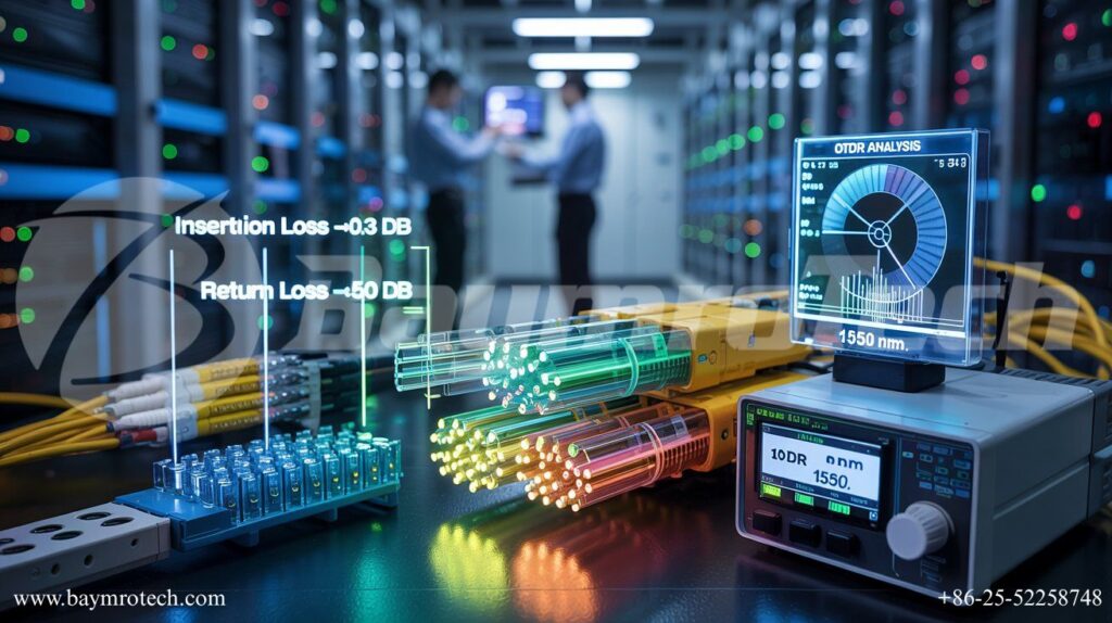
In plain terms, IL is calculated in decibels (dB) as IL = 10 * log10(Pin / Pout), where Pin is input power and Pout is output power. Typical acceptable values hover under 0.3 dB per connector in high-speed networks. I remember troubleshooting a client’s data center last year; their IL spiked to 0.7 dB from dirty connectors, turning gigabit speeds into molasses—we fixed it with a quick clean, and boom, full speed restored.
- Causes: Misaligned fibers, dirty ends, or mismatched core sizes.
- Impact: Higher IL means weaker signals over distance, forcing costly amplifiers.
- Pro Tip: Always test with an optical power meter post-install.
Decoding Return Loss
Return loss (RL) is the opposite headache—it’s how much light bounces back toward the source due to reflections from imperfections, like air gaps or poor polish. Higher RL is better here (e.g., >50 dB is gold standard), as it means less reflection messing with your laser source.
Formula-wise, RL = -10 * log10(Pr / Pi), with Pr as reflected power. Imagine shouting into a canyon; too much echo (low RL) garbles your message. In one funny install I oversaw, a tech used mismatched UPC/APC connectors—RL tanked to 30 dB, and the whole link flickered like a bad horror flick. Swapping them bumped RL to 60 dB, stabilizing everything.
Why care? Poor RL destabilizes transmitters, increasing bit errors in 10G+ networks.
Other Key Fiber Performance Metrics
Fiber isn’t just IL and RL—it’s a team effort. Here’s the lineup that keeps your network humming:
- Attenuation: Total fiber loss per kilometer, typically 0.2–0.4 dB/km at 1550 nm.
- Optical Return Loss (ORL): Cumulative RL across the entire link, critical for long-haul.
- Chromatic Dispersion: How wavelengths spread, limiting speed over distance.
- Polarization Mode Dispersion (PMD): Signal skew from fiber imperfections.
For hybrid setups, Copper/Fiber Composite Cable shines by blending copper reliability with fiber speed, minimizing these metrics in power-comms hybrids. Check our guide on fiber optic installation best practices for deeper dives.
Real-world stat: Networks with IL under 0.2 dB see 30% fewer outages, per industry benchmarks.
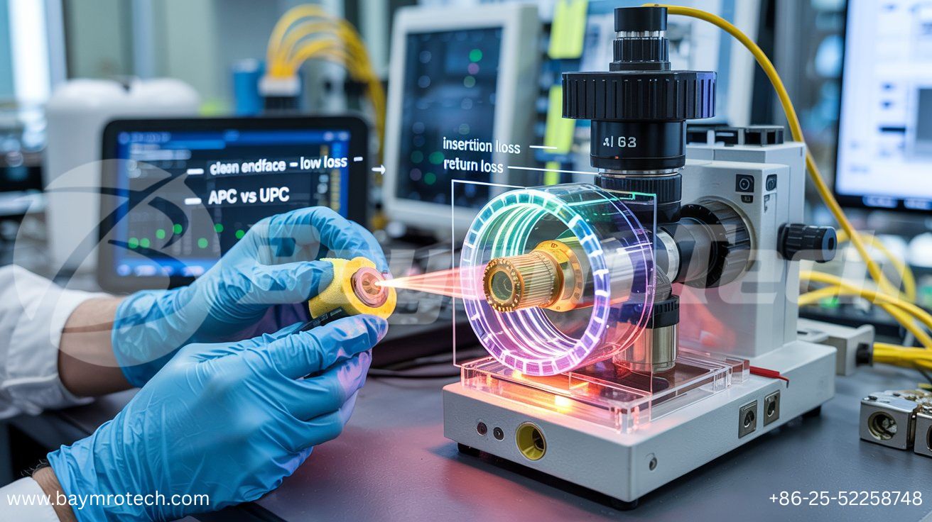
This close-up of a fiber connector reveals why cleanliness is king—specks here amplify IL dramatically.
Why These Metrics Matter in Real Networks
Picture this: You’re rolling out a 100G backbone for a bustling office in Kolkata. Ignore IL/RL, and your “future-proof” link chokes on video calls and cloud backups. These metrics directly dictate bandwidth, error rates, and uptime.
In FTTH deployments, standards like IEC 61300-3-4 cap IL at 0.3 dB for singlemode. For data centers, even 0.1 dB extra per link adds up—24 connections? That’s 2.4 dB lost, halving your budget.
Humor break: Ever blame the “internet gremlins”? Nope, it’s often sneaky RL reflections playing tricks. Learn more from Corning’s fiber optics guide, a gold standard resource.
How to Measure and Test Effectively
Testing isn’t rocket science, but skip it and regret follows. Grab an OTDR (Optical Time-Domain Reflectometer) for loss profiling or a power meter for quick IL checks.
Step-by-Step Testing:
- Clean connectors with isopropyl wipes—dirt causes 70% of IL issues.
- Reference your source and meter.
- Measure IL across each segment.
- Scan for RL with a source-launcher.
- Document everything.
Pro advice: For Copper/Fiber Composite Cable, test hybrid segments separately. Our cable testing protocols page details Baymro Tech’s methods.
External cred: Fiber Broadband Association offers free OTDR primers.
Minimizing Loss for Peak Performance
Ready to slash losses? Here’s your playbook, drawn from field wins:
- Polish Right: Use machine-polished ferrules; hand-polish invites gaps.
- Match Modes: Singlemode to singlemode only—mismatches kill RL.
- Bend Gently: Minimum radius 10x cable diameter to dodge macrobend loss.
- Splice Smart: Fusion splicing beats mechanical (0.02 dB vs. 0.1 dB typical).
- Hybrid Wins: Copper/Fiber Composite Cable reduces splices in power networks.
One client slashed IL by 40% post-cleaning routine—pure magic! For stats, Lightwave Magazine reports clean networks boost lifespan 2x.
| Metric | Target (Singlemode) | Common Culprit | Quick Fix |
|---|---|---|---|
| Insertion Loss | <0.3 dB/connector | Dirt/Gaps | Clean & Align |
| Return Loss | >50 dB | Poor Polish | APC/UPC Upgrade |
| Attenuation | <0.35 dB/km | Fiber Quality | Premium SMF-28 |
A pristine fiber endface under microscopy—your goal for minimal IL and max RL.
Advanced Tips for Pros
Scaling up? Consider DWDM systems where PMD bites harder. Use Baymro Tech’s fiber solutions for low-loss composites in electric infrastructure.
Quote time: “Reflection is the thief of performance,” notes a Newport Photonics expert. Empathy check: I get the frustration—late-night traces suck. But mastering these metrics? Empowering.
Wrapping It Up
Insertion loss saps your forward signal, return loss fights reflections, and together with attenuation and dispersion, they define fiber health. Prioritize cleaning, matching, and testing to hit targets like <0.3 dB IL and >50 dB RL.
Ready to upgrade? Explore Copper/Fiber Composite Cable at Baymro Tech, contact our team for a custom audit, or drop your toughest fiber question in the comments—we’re here to help!


