
Selecting the right enclosure for an outdoor application for the first time can be a daunting task and should be addressed with a systematic approach in order to minimize problems in the field. Once the enclosure has been placed in the field the number of options becomes limited and often expensive to correct. This document is intended to provide a check list up front for the initial design to eliminate as many issues prior to installation as possible.
ENCLOSURE SIZE: The physical size of the enclosure is normally determined by the amount of equipment that is required to implement the application. Often times the potential for expansion of the application in the near future is not considered and generally speaking should be considered to be in the range of 10% to 20% for expansion.
ENVIRONMENT: The environment that the enclosure must operate in is an extremely critical item and often times the “one size fits all” approach can be expensive in a large build out. It is often best to have two or three designs to handle the various environments to reduce overall system deployment costs and reduce the operating and maintenance costs as well.
(1). Environments that the ambient rarely exceed 100 degree F (38 deg C).
(2). Environments that the ambient regularly exceed 100 degrees F (38 deg C).
(3). Environments that have caustic chemical exposure such as industrial fallout and salt water.
The type (1) environment above is typically a good match for the Direct Air Cooled cabinet as long as the equipment heat load is within the operating range of the equipment. The basic advantage of this approach is reduced system cost as well as lower maintenance and operating costs. The type (2) environment above is typically an air conditioned closed loop system that can handle the extreme ambient temperature. This approach does have higher system cost, higher maintenance cost as well as higher operating cost.
The type (3) environment above can be an air conditioner or heat exchanger cooled system. This is a closed loop system and the selection between the air conditioner and the heat exchanger is dependent on the system heat load requirement. The selection of the heat exchanger significantly reduces the initial system cost, maintenance and operating cost.
EQUIPMENT PLACEMENT: The placement of equipment in the enclosure rack rails can be an extremely important factor in the distribution of heat within the enclosure. It is best to have the highest heat producing equipment located toward the top of the enclosure so that this heat is not subjected to the other equipment. Air flow is also a critical item and most equipment manufacturers will require a minimum of 1RU clearance above and below the equipment. Air intake and exhaust of equipment with fans requires convection cooling and needs to be placed in the cool air flow of the enclosure. Equipment that the intake and exhaust are located on the sides may require special air ducting to properly provide cooling.
OPEN LOOP COOLING: Open loop cooling typically draws air into the enclosure at the bottom of the enclosure and exhausts the air out of the top of the enclosure. The input air must be filtered to reduce contamination of the enclosure by dust, salt, fog and other contaminants.
CLOSED LOOP COOLING: Closed loop cooling, as its name implies, is where the enclosure air is circulated internally and no air is taken in from the outside environment. This is typically done with an air conditioner or heat exchanger.
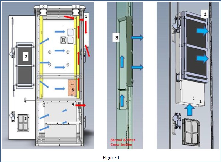
DIRECT AIR COOLING: Direct Air cooling (DAC) can be a low-cost method of cooling the equipment in the enclosure at temperatures above the ambient air temperature. This process is done by low-cost fans that are L10 rated (50,000 hours). The fans require very little current to operate and therefore are low in operating cost and easy to replace in the field. Maintenance of the filter is typically a 30 to 60-day event with replacement of the filter between 6 months to a year depending on the outside air quality. The general rule is that the sum of the ambient temperature, solar load, and the equipment heat load is within the operating range of the equipment for the DAC approach to be suitable; sample airflow below.
ENCLOSURE SIZE: The physical size of the enclosure is normally determined by the amount of equipment that is required to implement the application. Often times the potential for expansion of the application in the near future is not considered and generally speaking should be considered to be in the range of 10% to 20% for expansion.
ENVIRONMENT: The environment that the enclosure must operate in is an extremely critical item and often times the “one size fits all” approach can be expensive in a large build out. It is often best to have two or three designs to handle the various environments to reduce overall system deployment costs and reduce the operating and maintenance costs as well.
(1). Environments that the ambient rarely exceed 100 degree F (38 deg C).
(2). Environments that the ambient regularly exceed 100 degrees F (38 deg C).
(3). Environments that have caustic chemical exposure such as industrial fallout and salt water.
The type (1) environment above is typically a good match for the Direct Air Cooled cabinet as long as the equipment heat load is within the operating range of the equipment. The basic advantage of this approach is reduced system cost as well as lower maintenance and operating costs. The type (2) environment above is typically an air conditioned closed loop system that can handle the extreme ambient temperature. This approach does have higher system cost, higher maintenance cost as well as higher operating cost.
The type (3) environment above can be an air conditioner or heat exchanger cooled system. This is a closed loop system and the selection between the air conditioner and the heat exchanger is dependent on the system heat load requirement. The selection of the heat exchanger significantly reduces the initial system cost, maintenance and operating cost.
EQUIPMENT PLACEMENT: The placement of equipment in the enclosure rack rails can be an extremely important factor in the distribution of heat within the enclosure. It is best to have the highest heat producing equipment located toward the top of the enclosure so that this heat is not subjected to the other equipment. Air flow is also a critical item and most equipment manufacturers will require a minimum of 1RU clearance above and below the equipment. Air intake and exhaust of equipment with fans requires convection cooling and needs to be placed in the cool air flow of the enclosure. Equipment that the intake and exhaust are located on the sides may require special air ducting to properly provide cooling.
OPEN LOOP COOLING: Open loop cooling typically draws air into the enclosure at the bottom of the enclosure and exhausts the air out of the top of the enclosure. The input air must be filtered to reduce contamination of the enclosure by dust, salt, fog and other contaminants.
CLOSED LOOP COOLING: Closed loop cooling, as its name implies, is where the enclosure air is circulated internally and no air is taken in from the outside environment. This is typically done with an air conditioner or heat exchanger.
DIRECT AIR COOLING: Direct Air cooling (DAC) can be a low-cost method of cooling the equipment in the enclosure at temperatures above the ambient air temperature. This process is done by low-cost fans that are L10 rated (50,000 hours). The fans require very little current to operate and therefore are low in operating cost and easy to replace in the field. Maintenance of the filter is typically a 30 to 60-day event with replacement of the filter between 6 months to a year depending on the outside air quality. The general rule is that the sum of the ambient temperature, solar load, and the equipment heat load is within the operating range of the equipment for the DAC approach to be suitable; sample airflow below.
AIR CONDITIONING: The use of an air conditioner which is always a closed loop system and will maintain the temperature of the equipment based on the set point entered in the air conditioning system. The air conditioner is a complex mechanical system that depends on temperature conversion due to the transfer of heat using a gas compression system. The air conditioned approach has higher initial cost with attendant maintenance cost as well as higher operating cost. Typically, air conditioning is used when the ambient temperature regularly exceeds 100 degrees F and the system heat load is sufficient that the temperature in the enclosure will exceed the environmental limits of the equipment without using an air conditioner. Air conditioners also require routine filter maintenance on an interval of 30 to 60 days; depending on local conditions.
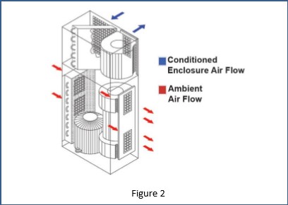
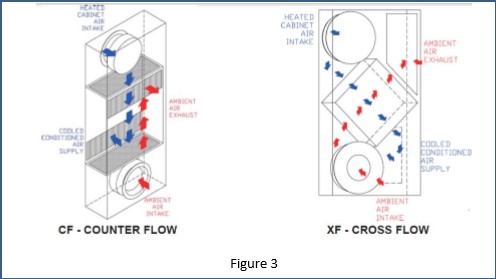
HEAT EXCHANGER: The heat exchanger is a closed loop cooling method that uses fans to transfer heat through a heat sync transfer material that is connected to the inside of the enclosure. Typically there are fans inside the enclosure to move air through the heat sync and fans outside the enclosure to move ambient air over the heat sync to transfer heat to the outside. The heat exchanger uses low cost fans and requires little electrical current to operate and thus has extremely low operating cost. The replacement of the fans can be performed at the field level and are low cost as well. The disadvantage to a heat exchanger is the limit of ambient temperature and system heat load to be able to maintain a temperature that is within the operating temperate range of the equipment.
HEAT VS. MTBF: The Mean Time Between Failure (MTBF) actually got started in the early 1960’s as a method by the military to increase the reliability of equipment. The idea was to evaluate each individual component in a system (resistors, diodes capacitors, and transistors) and then statistically take the root sum square (RSS) of all the components to develop a system MTBF. Essentially, the way this was done was to test the component at a temperature much higher than the component design limit and see how long it took to fail and using an algorithm to determine an MTBF for the component. This caused manufacturers to design the components to operate at a much higher temperature so that their component would have a higher MTBF than their competitors. Today’s Military Standard and industrial grade components are designed to operate at much higher temperatures than the advertised values and therefore have higher MTBF ratings than their original components. The basic concept of MTBF is that for each 10 degrees C rise in temperature the component MTBF is reduced by 50%. Conversely, if you reduce the temperature by 10 degrees C the MTBF doubles which encourage the system designer to keep the system temperature as low as possible to extend the system life of the equipment.
CONTROLLING CONDENSATION: Condensation can be a significant issue that over time can degrade the performance of the system. Condensation will form on the equipment if the temperature in the enclosure is at or below the dew point. The dew point is a function of the temperature and relative humidity (RH %) inside the enclosure and the difference between the dew point and the temperature gets less as the RH% increases. Typically this is due to cool moist outside air that is drawn into a Direct Air Cooled enclosure and there is insufficient heat load temperature within the enclosure to prevent condensation. The most efficient method of controlling condensation in an enclosure is to maintain a temperature of between 95 to 104 degrees F to prevent the moisture in the air to condense due to the level above the dew point.
The temperature range of 95 to 104 degrees F does have a negative effect on MTBF; however, keep in mind that MTBF is developed at an RH of less than 50% where condensation will not occur. This is a tradeoff that the system designer must consider in the design.
The effects of condensation with current day electronic components, especially large scale integrated circuits, are extremely critical due to the small displacement of pins on the components. The condensation is fresh water with a resistance of about 5,000 ohms per centimeter conductivity which can degrade the performance of components and possibly lead to failures of the components. Condensation will also combine with other chemicals on the printed circuit boards and can become caustic and may eventually cause the destruction of signal and power lands on the boards.
There is a common misconception in the industry that salt and fog filters will reduce or eliminate moisture/humidity in the enclosure and thereby prevent condensation. Further hydrophobic filters will prevent water incursion but have no effect on moisture/humidity. The reason is simply that moisture is part of the air that passes through the filter and the conversion from the gas state to the liquid state of condensation is purely dependent on the temperature of the dew point.
Welcome to contact us for obtaining customized solution of the outdoor enclosure.


1 Comment
I see you don’t monetize baymrotech.com, don’t waste your traffic, you can earn extra cash every month with new monetization method.
This is the best adsense alternative for any type of website (they approve all sites), for more info
simply search in gooogle: murgrabia’s tools